 |
Submitting assignments |
Schedules | Course Info | Ch. Reviews | Guides | Problems | Labs | Videos | AP Info | |
| Announcements | Contact | Shortcuts | WebAssign | Canvas | Equations | Lab FAQ | Software | IWP |
|
Goal
To determine both theoretically and experimentally the currents and potential differences in a combination circuit of 3 resistors
Prelab
The theoretical foundation for what you will do in this lab is found in Solving Multiloop Circuit Problems.The prelab deals with the theory. Do the following.
- Do L165PL on paper to scan and submit to BrainHoney. You'll analyze the circuit assigned to you below. See the instructions that follow.
ID Circuit to analyze Assigned to Circuit A Last initials B - N Circuit B Last initials R - W You'll provide a complete circuit analysis for the circuit assigned you. In checking your work, the instructor will be looking for i) a clear and logical organization of your work, ii) proper use of subscripts for voltages, currents, and resistances, and iii) demonstrated and correct use of the loop and junction rules.
Do the following for your assigned circuit.
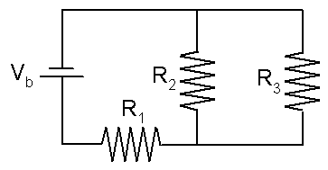
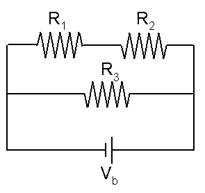
- Draw a circuit diagram and label it using the same symbols as above. Make sure that R1, R2, R3 are labeled as in the diagram above.
- Clearly identify the loops and junctions that you use in your theoretical derivations.
- Show and clearly identify your use of loop and junction rules.
- Combine equations and do algebra as necessary to write equations for I1, I2, I3, V1, V2, V3 in terms of these symbols only: Vb, R1, R2, R3, Req.
- List all your equations in a table like the following. Include the equation for the equivalent resistance of the circuit in terms of R1, R2, R3.
Req = I1 = I2 = I3 = V1 = V2 = V3 =
Follow up on the prelab
After the instructor checks your prelab solution and posts comments, do the following as indicated in order to complete preparations for the lab.
- Complete and correct your solution as indicated. If you didn't show the use of loop or junction rules, you'll need to revise your solution in order to explicitly show how you use these circuit rules.
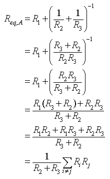
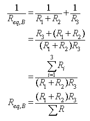
- If you didn't express your tabulated results in reduced form, you'll need to reduce them algebraically. It will help in this regard not to use Req in the final expressions. Instead, write Req in terms of the individual resistances and collect terms. This will involve adding fractions. See the following for a way to express Req compactly for the two circuits.
Circuit A The summation notation in the final expression is a way to compactly express the sum of the resistance products. The summation is interpreted as follows: Add all possible products of Ri and Rj for which i does not equal j. Circuit B The sum of the three resistances is expressed compactly by the summation symbol.
Equipment
- Multimeter
- 470 Ω, 1000 Ω, 2700 Ω resistors
- 4 batteries and battery holder(s)
- 4 alligator clip wires
Data and Calculations
Download this file and print it. Then carry out the instructions in the file. See these photos for guidance in building your circuit and measuring current.
© North Carolina School of Science and Mathematics, All Rights Reserved. These materials may not be reproduced without permission of NCSSM.