 |
Submitting assignments |
Schedules | Course Info | Ch. Reviews | Guides | Problems | Labs | Videos | AP Info |  |
| Announcements | Contact | Shortcuts | WebAssign | Canvas | Equations | Lab FAQ | Software | IWP |
|
About your report: Write your answers to the numbered items on notebook paper. Provide the usual heading for your report.
Goal
To investigate the characteristics of resistors wired in series and parallel circuits
Equipment
Multimeter
Selection of resistors
Batteries and battery holder
Alligator clip wires
Preparation
Review the proofs in Conservation Laws in Circuits of the general formulas for the equivalent resistance, Req, of two resistors in series and in parallel. Note how each of these proofs applies the laws of conservation of charge and of energy. Review section 21.4 of the text as needed to see how to extend the formulas to circuits with more than two resistors.
Part A: Exploring Resistances in Series
- Gather four different resistors between 470 Ω and 10,000 Ω. Measure and record the resistance of each of your resistors. Assign the resistors the labels R1 to R4 in order of increasing size for bookkeeping purposes. Since you're using a meter for your measurements, report all the digits in the meter readout. Don't rely on the color code.
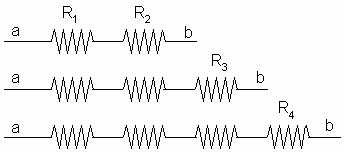
- Measure and record the equivalent resistance of two, three, and four different resistors connected together as shown in the three diagrams below. Connect the resistors with clip leads. Use the resistance measuring function of the meter, and touch the meter probes to the points a and b. Make it clear what measurement goes with what diagram.

- You should see a trend in how the measured equivalent resistance relates to the individual resistance values. From the trend you observed, write down a sentence describing the trend (qualitative words only, no math). Your sentence should be something like: "As the number of resistors in a series increases, the equivalent resistance of the combination....
- Write a general formula for the equivalent resistance, Req,ser, of N resistors (R1, R2, R3,...,RN) in series.
- To test the formula, assume resistors R2 and R3 alone are placed in series. Use your formula to calculate the equivalent resistance.
- Now connect R2 and R3 in series and measure the equivalent resistance with the multimeter. Then find the percentage difference between predicted and measured values. Use the formula given in Lab FAQ.
- Draw a circuit diagram for a series circuit of resistors R2 and R3 and 4 batteries. Using the loop rule, the junction rule, the definition of resistance R = -ΔV/I, and/or the equivalent resistance formula you determined in step 4, obtain equations for the following quantities in terms of R2, R3, and the battery voltage, Vb: a) current in R2, b) current in R3, c) potential difference across R2, d) potential difference across R3. Show where in your work you use the loop or junction rules. Show your work clearly in symbols only (no numbers yet). Use subscripts as needed to distinguish between different currents and potential differences. Label these quantities on the circuit diagram.
- Now connect the circuit of step 7 and measure quantities a) - d). Record your measurements. Compare to your predicted values. Organize all of your results neatly in a table in which you provide columns for resistance, predicted values, measured values, and percentage differences.
Part B: Exploring Resistances in Parallel
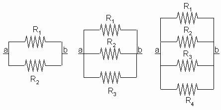
- Using the same 4 resistors as in Part A, connect each of the parallel combinations shown below and measure the equivalent resistance by touching the meter to points a and b.

- Again, you should see a trend in the measured resistance values. From the trend you observed, write down a sentence describing the trend (words only, no math). Your sentence should be something like: "As the number of resistors in parallel increases, the equivalent resistance of the combination...."
- Write a second full sentence describing how the equivalent resistance always compares to the smallest individual resistance in the parallel combination.
- Write a general formula for the equivalent resistance, Req,par, of N resistors (R1, R2, R3,...,RN) in parallel.
- To test the formula, assume resistors R2 and R3 alone are placed in parallel. Use your formula to calculate the equivalent resistance.
- Now connect R2 and R3 in parallel and measure the equivalent resistance with the multimeter. Find the percentage difference between predicted and measured values.
- Draw a circuit diagram for a circuit of resistors R2 and R3in parallel with 1 battery. Using the loop rule, the junction rule, the definition of resistance R = -ΔV/I, and/or the equivalent resistance formula you determined in step 4, obtain equations for the following quantities in terms of R2, R3, and the battery voltage, Vb: a) current in R2, b) current in R3, c) potential difference across R2, d) potential difference across R3. Whenever you use the loop or junction rules, indicate this in your work. As in Part A, show your work in symbols. Label the currents and potential differences on the circuit diagram.
- Now connect the circuit of step 7 and measure quantities a) - d). Record your measurements. Compare to your predicted values. Organize all of your results in a table as in Part A.
Part C: A Test of What You Learned
Obtain three resistors of nearly equal value. The three 1000-ohm resistors provided you can serve this purpose. Measure and record their resistance values. Using all three of these resistors, construct four different combinations, each yielding a unique equivalent resistance value. For each combination, a) draw the circuit diagram, b) calculate the equivalent resistance of each combination, c) measure the equivalent resistance with the multimeter, and d) compare (find % diff.) to the calculated values. Organize your results in a table.
© North Carolina School of Science and Mathematics, All Rights Reserved. These materials may not be reproduced without permission of NCSSM.