About your report: Write your report on paper to scan later. Number the items of your report the same as numbered in the instructions.
Goals
- to light a bulb
- to experimentally show that an incandescent light bulb does not obey Ohm's Law
- to determine the temperature of the bulb filament
Equipment
Multimeter
Light bulb and holder
4 1.5-V batteries and battery holder(s)
Clip wires
Prelab
- Successfully complete the Multimeter Tutorial.
- Read the introduction to this lab.
- Read sections 21.2,3 of the text.
- Watch this video to see what happens when a lit bulb is shot with a BB. (Don't try this with your bulbs at home!) When exposed to oxygen, the filament bursts into flame.
Introduction
 The Definition of Resistance
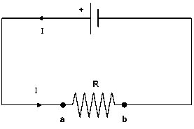
The definition of electrical resistance is R = -ΔVr/I, where ΔVr is the potential difference across the resistor when conventional current I passes through the resistor. Consider the simple circuit with a battery and resistor shown to the right. Conventional current leaves the battery from the positive terminal and passes through the resistor from left to right. Point a has higher potential than point b, so the difference of potential across the resistor is ΔVr = Vb - Va < 0. It's conventional practice when measuring voltage with a meter to place the positive probe at the higher potential side. If we call V the voltage measured by a meter in this way, then V = Va - Vb > 0. Therefore, V = -ΔVr > 0. With this definition of voltage V as measured by a meter, the definition of resistance is R = V/I. As you can see, there's potential (no pun intended) to get confused by the meanings of V and -ΔVr, besides the fact that V also represents the unit of the volt. We summarize these results in the table below.
| Symbol | Description | Used in a formula | Notes |
| ΔVr | potential difference across a resistor | R = -ΔVr/I | These are alternative ways to express the definition of resistance. |
| V | voltage as measured by a meter with the positive probe touched to the higher potential side | R = V/I | |
| V | unit of volt | V = 12 V | In typed text, the symbol for the variable V is italicized and the symbol for the unit V is not. |
Resistance of a Wire
The above is a treatment of the subject of electrical resistance in general. As a definition, R = -ΔVr/I applies to any electrical resistor. In the specific case of a wire, the resistance can be determined from physical characteristics of the wire: length, cross-sectional area, type of material. The resistance of a wire is given by R = ρL/A, where ρ is the resistivity of the material, L is the length of the wire, and A is the cross-sectional area of the wire. A fact mentioned only briefly in the text is that the resistivity is temperature dependent. The resistivity at temperature T is given by ρ = ρo[1 + α(T - To)], where ρo is the resistivity at some reference temperature (typically 20 °C), and α is the temperature coefficient of resistivity of the material and is relatively constant. The units of α are °C-1. For a wire of given length and cross-sectional area, the resistance will increase with temperature if α is positive. This fact is exploited in this experiment in order to determine the temperature of an incandescent bulb filament.
To Obey Ohm's Law or Not
|
Something to keep in mind as you read section 21.2 of the text is that the so-called Ohm's Law is not a physical law in same sense as Coulomb's Law or the law of gravitation. We think of a physical law as something that nature always obeys. Ohm's Law is really more a rule in the sense that many circuit elements don't obey it. In modern electronic circuits, in fact, Ohm's Law is probably violated more often than not. This is not to say that the relationship R = V/I isn't valid. You can always use that, because it's the definition of electrical resistance.
In order to determine whether a circuit element obeys Ohm's Law, one measures the current in the element as a function of the potential difference across the element. If a graph of current vs. potential difference is linear, then the circuit element obeys Ohm's Law. Here is the statement of Ohm's Law that you should remember:
|
In order to determine in an experiment if a particular resistor obeys Ohm's Law, you would connect the resistor in a simple circuit to different numbers of batteries. For each number of batteries, you would measure the current in the circuit and the potential difference across the resistor. If you use the conventional method of placing the positive probe of the meter on the higher potential side of the resistor, then you would be measuring voltage, V. The voltage would be the independent variable and would be plotted on the horizontal axis in a graph of I vs. V. If the graph were linear, one would expect the slope of the linear fit to be 1/R. (Why wouldn't you expect the slope to be -1/R?)
 Power Dissipation in Resistors and Incandescent Bulbs
The power provided by a battery is Pb = I|ΔVb|, where ΔVb is the potential difference across the battery terminals, and I is the current in the circuit. The power dissipated in a resistor is Pr = I²R. An alternative formula is Pr = (ΔVr)²/R, where ΔVr is the potential difference across the resistor. (See Guide 21-1b.) The same symbol I is used in both cases, because the current is the same in the battery and the resistor. In a given amount of time, Δt, the energy provided by the battery is Ub = PbΔt, and the energy converted by the resistor to heat is Ur = PrΔt. If we assume that the wires have negligible resistance and therefore negligible power dissipation, then for energy to be conserved, Ub - Ur = 0. Since the time interval is the same, Pb = Pr also.
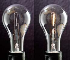
An incandescent bulb is a resistor. The tungsten filament of the bulb is designed to get so hot that it gives off light when current passes through it. See the side-by-side photos to the right showing the filmament with current off and on. Due to the fact that the resistance of the filament is temperature-dependent, incandescent light bulbs do not obey Ohm's Law.
Incandescent light bulbs convert electrical energy to two other forms: thermal energy and radiant energy (light). Taking light to be the useful energy output of the bulb, the efficiency of an incandescent bulb is the ratio of radiant energy output to electrical energy input. For typical incandescent bulbs, this is very low, only a few percent. This low efficiency is a primary reason for the switch to fluorescent bulbs, which have efficiencies as much as 4 times greater.
Part A. Lighting the bulb
|
 |
|
|
|
 |
Part B. Determining whether the bulb obeys Ohm's Law
Before making resistance, voltage, and current measurements, review the multimeter tutorial for how to connect the probes to the meter and to the circuit.
-
First, you'll measure what we call the room-temperature resistance of your light bulb, that is, the resistance when the bulb isn't lit. Ideally, you need to know the resistance of your bulb when no current is passing through it. In this case, the bulb will be at room temperature, which is typically 20 - 25 °C. However, when you connect your meter to the bulb to measure the resistance, the meter passes a small current through the bulb.This will heat the filament slightly and change its resistance. In order to minimize this effect, don't leave the meter connected for a long period of time while you measure the resistance. Just hold the leads in place long enough to get a stable reading. Record the reading as Ro.
- Measure the voltage across the bulb for 1, 2, 3, and 4 batteries. (Will the voltage be positive or negative? If you don't know the answer, review the Introduction.) Record your results in a table like the following.
Room temperature resistance, Ro = _________ ohm No. of batteries Voltage V across bulb
(V)Current I in bulb
(A)1 2 3 4
-
Now measure the current the circuit for the same 4 combinations of batteries and record in the table. Remember to break the circuit and change the position of the red probe for measuring current.
-
Plot a graph of I vs. V in Logger Pro. Set both of the scales to start from the origin. (Which variable will go on the horizontal axis?) You won't turn in this LP file. Instead, include the following in your report: A half-page size, hand-drawn graph of I vs. V for the bulb. You don't have to show grid lines, but do draw the axes with a straightedge, number the scales, and place the 4 data points in approximately correct locations. The origin must show on your graph, as this is important to the interpretation in the next item.
-
We know that the current should be 0 when the voltage is 0. If the origin were in fact a data point, describe the overall trend of the data. Which way would the best-fit line passing through the origin and the data curve? How would the slope change with increasing potential difference? From this examination, describe how the resistance of the bulb changes with V and explain how you know this.
Part C. Calculating the temperature of the filament
-
Using relationships from the introduction as starting points, show that for a wire of a given length and cross section, the wire's resistance is given by: R = Ro[1 + α(T - To)].
-
Look up the value of the temperature coefficient of resistivity for tungsten.
-
Calculate the highest temperature that the bulb filament reached. Start with a formula, solve for T, and show your substitutions. Round to appropriate significant figures.
Conclusion
Summarize what you did and what you learned in this lab.
Submitting your work
Scan and upload your report to BrainHoney.