Don't try this at home! |
Goal
Measure the speed of a bullet using a ballistic pendulum.
Prelab
Study the guide Solving Problems using both Conservation of Momentum and Energy first. Then answer the questions below in the WebAssign assessment L137PL. Keep in mind the following conditions.
|
-
Why was the author's use of conservation of momentum in Example 9-5 of the text valid? In order to answer, do the following.
-
Suppose the system is composed of the object and the bob. What external forces act on the system?
-
Is the net, external force on the system 0 during the collision? Explain. Assume that the collision refers to the very brief interval of time when the object is combining with the bob. The collision is essentially complete as the upward swing begins.
-
Is momentum conserved for the system chosen?
-
-
Now consider the upward swing after the collision. The initial state is when the collision is complete and the object-bob combination has its maximum velocity. The final state is when the combined object reaches its highest point. Should mechanical energy be conserved in the upward swing? In order to answer, do the following.
-
Take the system to be the object, bob, and Earth. State the one, external force acting on the system.
-
Does the force that you gave in part a do work on the system? Explain.
-
Is mechanical energy conserved for the system chosen?
-
-
Explain how you can tell by the nature of the collision that kinetic energy is not conserved in this collision.
-
These two questions relate to Example 9-5 in the text.
-
Which one(s) of the three conservation laws that we've studied this year did the author use in his solution?
-
The unknown in the textbook example is the height to which the pendulum rises. For this lab, however, the unknown is the velocity of the bullet. Solve the equation for v0.
-
Designing a real ballistic pendulum to measure the speed of a projectile involves more than the theory in the textbook. If the projectile is particularly fast, such as a bullet, then the pendulum bob needs to be massive and there has to be a way to prevent it from swaying from side-to-side after the collision. The length of the pendulum generally needs to be long in order to provide a correspondingly large horizontal displacement. The latter is used as a measure of the vertical displacement, because the vertical displacement is generally too small to measure accurately.
- With the above in mind, view the video clip Measuring the Speed of a Bullet with a Ballistic Pendulum: Streamed / RealPlayer / Flash. (You may want to turn down the audio for the gunshots.) As you watch the clip, some items of data are given. Record the values as they're given. After you've finished watching the clip, convert the values to SI units and enter them in WebAssign. (The horizontal distance between the upper pendulum supports won't be needed.) Here is a handy units converter: http://www.metric-conversions.org/weight-conversion.htm.
 Click on this link to open
a photo from the first shot. The photo is an overlay of two video frames.
One frame shows the log the instant before the bullet struck. The
other frame shows the log at the instant that it reaches its highest
position. The overlay makes it clear that the vertical displacement is
much smaller than the horizontal displacement. The percentage
uncertainty in measuring the vertical displacement would be much greater
than that in measuring the horizontal. Here is a situation where you
can make good use of the experimental maxim that it's usually better to
measure a larger value when possible.
Click on this link to open
a photo from the first shot. The photo is an overlay of two video frames.
One frame shows the log the instant before the bullet struck. The
other frame shows the log at the instant that it reaches its highest
position. The overlay makes it clear that the vertical displacement is
much smaller than the horizontal displacement. The percentage
uncertainty in measuring the vertical displacement would be much greater
than that in measuring the horizontal. Here is a situation where you
can make good use of the experimental maxim that it's usually better to
measure a larger value when possible.
-
In order to use the equation found in 4b above to calculate the speed of the bullet, you need to know the mass of the bullet, the mass of the log, and the vertical height through which the log rises. See the diagram to the right, which shows the initial and final states superimposed. The diagram exaggerates distance h. You saw from the photo that h was much smaller than the horizontal displacement, d. You'll be measuring d from the photograph, and you'll use that value to calculate h.
-
Do the geometry now to express h in terms of d and L.
-
Check your equation for i) units, ii) sign, iii) whether the expression under the square root is non-negative, and iv) whether h = 0 when d = 0.
-
Analysis
You'll do the remainder of the report using Logger Pro.
The plan of the analysis is to obtain the horizontal deflection from the video, scale it to the actual distance, and then use it together with other data from the video clip to obtain the speed of the bullet.
Determine the horizontal deflection as follows.
-
Download the photo overlay that you'll use: Shot 1 (for students with last initials from T to Z, A,C) Shot 2 (D-L) Shot 3 (M-S)
-
Open Logger Pro and select from the main menu: Insert -> Picture -> Picture with Photo Analysis. Navigate to the photo that you downloaded and insert it.
-
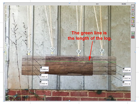
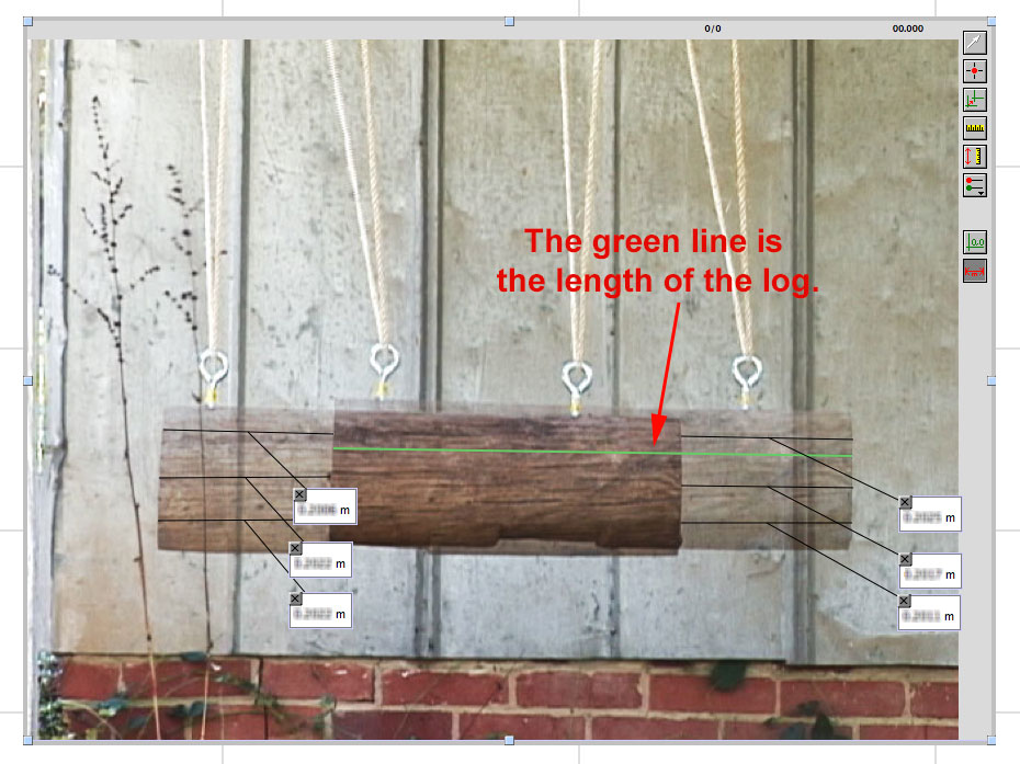
Drag the photo to a larger size for greater accuracy. You'll see two overlapping images of the log, one slightly higher than the other. Note that the region of overlap is darker than the rest of the log. Be careful not to confuse the region of overlap with the length of the entire log. The greeen line in the screen capture to the right is the length of the log. (Click on the photo for a larger image.)
-
Click on the Set Scale
 tool and drag across the length of the log. Release the mouse and then enter the actual length of the log in meters.
 -
Now you're ready to measure the distance d using the Photo Distance
 tool. Recall that d represents the horizontal deflection of the log. Measure this in 6 different locations as shown in the screen capture. Record the 6 values in the first column of the data table. For this and all columns of the data table, label and set the Displayed Precision appropriately.
-
-
Continue with the analysis as follows.
-
Delete the Y column in the data table. Then create a new calculated column in which you enter the formula to calculate the values of h.
-
Insert a text box. Give your Shot number. Follow that with the mean of your values of h.
-
Create another calculated column to calculate the deviations in h. Note that the absolute function is found in the statistics group.
-
Calculate the mean deviation and the % mean deviation in h. Write the values in the text box.
-
-
You have all the information you need to calculate the magnitude of the bullet's velocity. Do that now. Use the mean value of h.
-
Click here for a screen capture of the last shot with the heavier log. Insert the photo into your LP file for photo analysis. When you scale the photo, note that the distance given is the distance between the centers of the hooks rather than the length of the log. After scaling the photo, use the photo distance tool to measure the horizontal deflection. A single measurement will be sufficient.
-
From the photo, you can see that's impossible to discern visually how far the log rises. So you have no choice here but to use an indirect method. Rather than using the equation from 6a of the prelab, use the equation from 4b, solved for h. Use your calculated value of v0 to determine the value of h. This can serve as a reasonableness check on v0. Expect h to be ~ a millimeter.
Error Analysis
Create a new page for the Error Analysis and Conclusion.
Looking at the equation for v0, we see that there are 3 measurements that contribute to uncertainty: m, M, and h. You'll determine the uncertainty in each of these and then calculate the absolute uncertainty in v0. Keep these things in mind as you make your estimates and calculations:
- Use the data for the first thre shots, not the fourth one with the larger log.
- The mass of the log appears in a sum, (m + M). The mass, m, of the bullet is so small in comparison to the mass of the log, M, that we can simply ignore it in this sum. Therefore, the uncertainty in M will be the same as the uncertainty in (m + M).
- The mass of the bullet also appears in the denominator where we cannot ignore it. The manufacturer didn't provide an uncertainty for the value written on the side of the package; however, we might guess that hunters would expect good reproducibility in the speeds of bullets. Therefore, an uncertainty of no more than 1 grain would make sense.
- For the relative uncertainty in the height h risen by the log, use the % mean deviation that you've already calculated.
- When you calculate the relative uncertainty in v0, use half of the relative uncertainty in h. That's because taking the square root of something cuts the relative uncertainty by a factor of 2.
-
Now complete the uncertainties table. (Don't overlook question 2 under the table.)
-
Describe a potential source of error other than those resulting from the measurement uncertainties above.
| Measurement | Representative Value of Measurement |
Absolute Uncertainty |
Relative Uncertainty |
| Mass of the log | |||
| Mass of the bullet | |||
| Height risen by the log | |||
| Speed of the bullet |
Conclusion
Write a conclusion. In addition to the usual parts, describe in words how the formula for v0 was obtained using conservation of momentum and energy.
Submitting your file
Name your LP file L137-lastnamefirstinitial.cmbl. Check that the formatting and labeling is complete. Then submit the file to WebAssign L137.